|
|
Content | User documentation | Administrator documentation | Index of terms | Technical Support | Search on-line |
| FaxChange installation with PRI card Brooktrout TR114 |
Primary connection realized in combination of Brooktrout TRNIC and TR114 MVIP (this card isn't on the market anymore)
Card with telecommunication interface Brooktrout TR Network Interface Card realized telecommunication layer and supports protocols EuroISDN DSS-1 (ETSI ETS 300 403). For controlling of the basic layer is needed to install Brooktrout Enhanced Call Control 1.7.5 for TR114 with support of Bfv API 4.3. ( required by FaxChange 5.0) in next steps:
Put the cards into the slots, the best way is to put them side-by-side and connect them through flat 40 streak cable MVIP bus. (cable is included in TR NIC ship box). If there is less than 5 cards on the MVIP bus, then on the TR NIC card (PRI-PCI) has to be the J2 switch in the default setting and the card has to be on one end of the bus (Not Terminating ). The card on the second side of the bus has to be set in Clock Terminating mode (SW1-1 On, SW1-2 On). If there is more than 5 cards on the MVIP bus, you should put the TR NIC card anywhere on the bus. In this case you have to set Clock Terminating to ON on both sides of the bus!
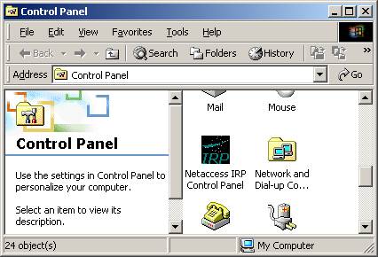
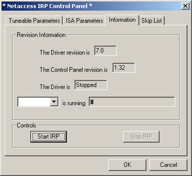
Run from your install CD \support\FaxChange\Brooktrout_PRI\ECC_1.7.5_TR114\Setup.exe , which will guide you through the NetAccess IRP driver and ECC 1.7.5 API installation.
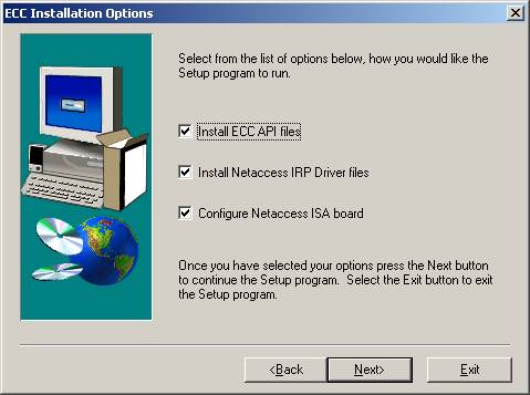
!!!! If you have TRNIC PCI card, then don't fill the choose Configure Netaccess ISA board !!!
Steps different to Microsoft Windows 2000 Server Family operating system
\support\FaxChange\Brooktrout_PRI\ECC_1.7.5_TR114\NAISYS_7.0_
          for_W2000\naidrv.sys
from install CD to folder %SystemRoot%\system32\drivers\ and
restart the server.
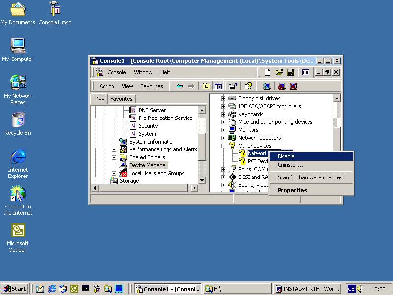
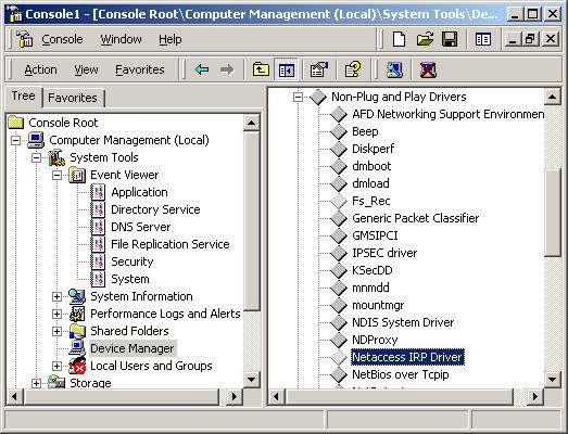
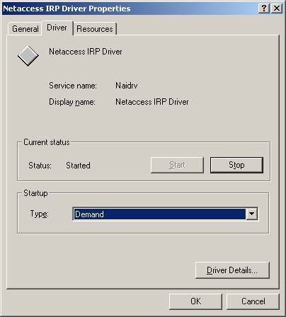
- Set his automatic starting in Device Manager.
Run the classic installation of FaxChange, where during the driver installation of Brooktrout card driver configure only TR 114 MVIP cards !
Do not forget, that every PRI connection should have maximally 30 channels, based on its configuration ( beware, you may configure less than 30, that why you should contact your PBX technician ). total amount of the connection defined in Brooktrout card driver have to correspond to number of channels available in PRI connection.
In case, that operating system is Microsoft Windows 2000 Server Family repair the file %SystemRoot%\bfax\config.sys
ADDRS 264 15
the first number define address and this number change every time to -1
ADDRS -1 15
After the successful install do not restart the server !!!
Run the installation from the directory where you install ECC. For FaxChange 5.0, which use Bfv API 4.3 it has to be run from subdirectory \server43 !!! Beware of difference between place of installation and default place of configuration files !!!
F:\Bfax\server\server43>btnasrv -install
Checking for required Services...
RPC installed.
TCP/IP installed.
BTNA Service installed.
1 board(s) found
Installing PCI board, using slot: 0f bus: 00
Enter name and location of the configuration file. [default: c:\bfax\server\btna.cfg] f:\bfax\server\btna.cfg
Enter location of the PRI.0 (isa) or NAII.0 (pci) firmware. [default: c:\bfax\server\] f:\bfax\server\
Enable debug log (y or n, default n): n
To start the service now, run 'net start BtnaService'
We do not recommend activating debug log, because the same effect have manual running on the console: \bfax\server\server43\btnasrv -d2.
Set in Services automatic start of the service. There is no need to run it yet.
Run from \support\FaxChange\Brooktrout_PRI.REG file the same as your operating system, which sets the dependency on the service FaxChange.LineDrvBT to start the BTNA Service.
- btna.cfg - configuration of the telecommunication interface
configuration is usable for protocol by ETS 300 403 with using CRC4.
If you left the default setting in folder \bfax\server\. Samples are in installation CD infolder \support\FaxChange\Brooktrout_PRI\ECC_1.7.5_TR114\Config_files
#
#board and port numbers start with 0 - not usable for one port card
# Configured for E1 PRI
#
bchanmap c:\bfax\server\bchanmap.cfg
[board 0 port 0] - defines physical port
board_type 2
switch_type 8
variant_type 6
call_type 99
network 0 - defines the role in communication with PABX, 0 - Slave, 1 - Master
[end]
[board 0 port 1] - this start use in case that on TR NIC is only one port
board_type 2
switch_type 8
variant_type 6
call_type 99
network 0
[end]
- bchanmap.cfg - Configuration file that sets the static mapping of B channels of PRI connection on MVIP bus
#
#
# E1 PRI
#
# Config file to setup b-channels
#
# Board port bchannel mvip_stream mvip_timeslot - MVIP Stream must cooperate with configuration file digital.cfg
#
0 0 1 6 0
0 0 2 6 1
0 0 3 6 2
0 0 4 6 3
0 0 5 6 4
0 0 6 6 5
0 0 7 6 6
0 0 8 6 7
0 0 9 6 8
0 0 10 6 9
0 0 11 6 10
0 0 12 6 11
0 0 13 6 12
0 0 14 6 13
0 0 15 6 14
0 0 17 6 15
0 0 18 6 16
0 0 19 6 17
0 0 20 6 18
0 0 21 6 19
0 0 22 6 20
0 0 23 6 21
0 0 24 6 22
0 0 25 6 23
0 0 26 6 24
0 0 27 6 25
0 0 28 6 26
0 0 29 6 27
0 0 30 6 28
0 0 31 6 29
0 1 1 4 0 - If you have card with only one port, starts the configuration on Bard 0, Port 1
0 1 2 4 1
0 1 3 4 2
0 1 4 4 3
0 1 5 4 4
0 1 6 4 5
0 1 7 4 6
0 1 8 4 7
0 1 9 4 8
0 1 10 4 9
0 1 11 4 10
0 1 12 4 11
0 1 13 4 12
0 1 14 4 13
0 1 15 4 14
0 1 17 4 15
0 1 18 4 16
0 1 19 4 17
0 1 20 4 18
0 1 21 4 19
0 1 22 4 20
0 1 23 4 21
0 1 24 4 22
0 1 25 4 23
0 1 26 4 24
0 1 27 4 25
0 1 28 4 26
0 1 29 4 27
0 1 30 4 28
0 1 31 4 29
- digital.cfg - configuration file which defines the bind between MVIP bus and physical DSP on TR114 - MVIP.
# 0 - 1.544 MHz
# 0 - 2.048 MHz
#
# sig_prot:
# 0 - E&M (AT&T PUB 43801) wink start.
# 1 - E&M (AT&T PUB 43801) immediate start.
# 2 - FXS, LOOP START MODE (AT&T PUB 43801)
# 3 - FXO, LOOP START MODE (AT&T PUB 43801)
# 4 - Exchange Access North America (FG_D_EANA)
# 5 - Exchange Access Intnl Signaling (FG_D_EAIN)
# 6 - Operator Service Signaling (FG_D_OS)
# 7 - Terminating protocol (FD_G_TERM)
#
# mf_freq:
# 0 - required for MVIP
#
# Note:
# For MVIP , clock_rate must be 2048 and robbed must be 0
#
1 0 0 1 6 0
# The rest of the lines contain: channel, tstream, tslot, (rstream, rslot). - tstream and rstream have to cooperate with bchanmap.cfg
0 6 0 6 0
1 6 1 6 1
2 6 2 6 2
3 6 3 6 3
4 6 4 6 4
5 6 5 6 5
6 6 6 6 6
7 6 7 6 7
8 6 8 6 8
9 6 9 6 9
10 6 10 6 10
11 6 11 6 11
12 6 12 6 12
13 6 13 6 13
14 6 14 6 14
15 6 15 6 15
16 6 16 6 16
17 6 17 6 17
18 6 18 6 18
19 6 19 6 19
20 6 20 6 20
21 6 21 6 21
22 6 22 6 22
23 6 23 6 23
24 6 24 6 24
25 6 25 6 25
26 6 26 6 26
27 6 27 6 27
28 6 28 6 28
29 6 29 6 29
Connect PRI connector and restart the server. Successful creating of frame synchronization of the PRI connector is signalized by switching on Run LED ( green ) and switching of all yellow LEDs of every channel A and B. It doesn't mean that there can't be a problem.
Correct state of functionality is signalized by writing BTNA service into Event Log with state of every ports, that they are UP.
If there is a state DOWN of some ports, you cannot you PRI connector !!!
set correctly configuration of PBX and TR NIC card. For successful reading configuration of TR NIC card you should restart BTNA service. If you still can't go on you have to use measure equipment to locate the problem.